How do pinball displays work?
An ordinary non dot-matrix display consists of digits and segments. The number of digits determines how long numbers or words to be displayed can be, while the amount of segments per digit determines whether charakters or only numbers can be displayed. Additionally each pinball machine contains multiple of these displays sometimes on a common board, sometimes separate.
Hence a Williams System 6 (e.g. Flash) has 4 single displays each with 6 digits and 8 segments per digit - 7 for the numbers and one for the comma. Furthermore it has a 4 digit credit display. On the other side a WPC alphanumeric (e.g. Fun House) has two displays, each with 16 digits and 15 segments - 14 for alphanumeric characters and one for the comma.
The way of working is similar to the lamp matrix. A strobe signal activates one single digit while the segment signals determine which segments of this digits shall shine. After that the next strobe signal becomes active and therefore the next digit. It is important to understand that only one digit is shining at the same time, that means they're more flashing than shining. Since this stepping through the digits happens very fast, the flashes are not discernible for our eyes any more. Instead we have the impression that all digits would shine continuously.
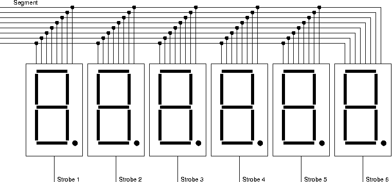
Therefore a 6 digit numerical display is built up as follows:
The segment signals of all digits are connected together and the strobe signals determine which digit is shining (flashing)
Difference between glas tube and LED control
In a nutshell, the main difference in the control of both kinds of displays is that glas tubes require high voltages while LEDs require large currents. For this reason a high voltage power supply is needed when glas tubes are used. It has to provide the necessary voltages of +- 100V. Furthermore special driver ICs are used to transform the 5V control signals form the CPU to high voltage signals. Most of the time an UDN6118 is used for the segment signals (90V) and an UDN7180A for the strobe signals (-100V). LEDs can work with the ordinary 5V supply, but they need up to 20mA for each shining LED (segment). For an alphanumerical display with 15 segments this can add up to 300mA. We used the ULN2803A to connect the cathodes of the activated segments to ground. The strobe lines are controlled by field effect transistors switching the strobe of the activated digit to the 5V supply. That means the non active digits stay dark as they're not supplied with 5V and the non active segments of the active digit stay dark since they have 5V but no current can float to ground.
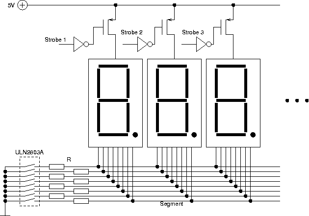
This picture shows the simplified structure of a circuit using common anode LED displays. The resistors R limit the currents floating through the LEDs and therefore determine the brightness. The complete circuit for one digit can be seen below it is just repeated for every digit.
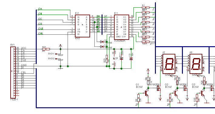
The schematic shows our design for early bally pinballs and contains some additional controllogic.